 EN
EN


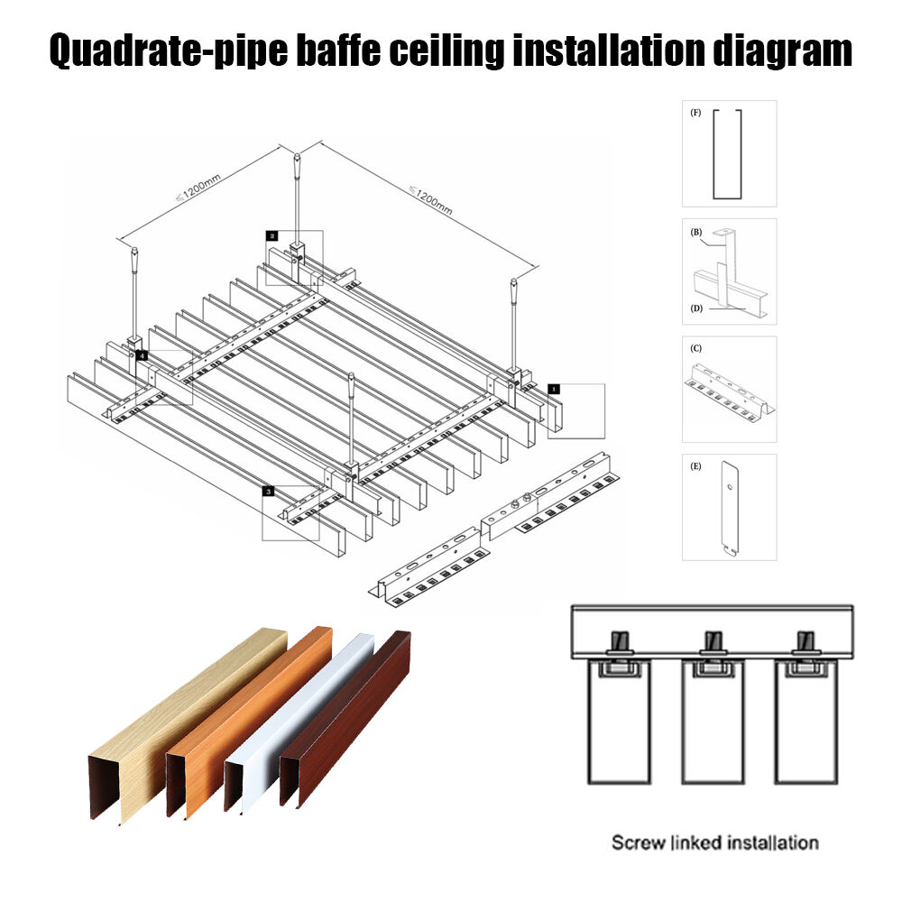
Aluminum baffle ceilings consistently rank among the most demanding ceiling systems to install correctly. The open, linear geometry that makes them visually compelling — long parallel fins suspended in precise rows — also means every misalignment, every inconsistent gap, every off-plumb fin is visible from across a room.
This guide is written for site contractors, project managers, and specification engineers who need a technically rigorous walkthrough: not just the sequence of steps, but the tolerances, decision points, and failure modes that determine whether a baffle ceiling installation earns client approval or triggers a rework call.
What follows covers the full installation lifecycle — from structural assessment through to QC sign-off — for aluminum baffle ceiling systems in commercial applications. The principles apply to office buildings, airports, retail centers, hospitals, and transit stations, though specific fire and acoustic requirements will vary by project specification and jurisdiction.
What Makes Aluminum Baffle Ceilings Different From Other Suspended Systems
Before walking through installation, it helps to understand what makes baffle ceilings structurally and logistically distinct from clip-in or lay-in systems.
A standard 600×600 mm clip-in tile sits flush in a grid and is largely self-correcting — minor discrepancies in grid alignment are hidden by the tile face. A baffle fin is a vertical element, typically 50–300 mm tall and 0.6–1.2 mm thick, suspended from a carrier channel. Its face is fully exposed on both sides. Any deviation in plumb, height consistency, or lateral spacing is immediately visible and, in a large-span space, optically amplified across the row.
This geometry also creates practical challenges that solid ceilings avoid:
- Hanger points must be precisely coordinated because carrier channels cannot be relocated once anchored
- MEP services in the plenum are visible through the open gaps — their positioning must be deliberately managed, not hidden
- Lighting, HVAC diffusers, and sprinkler heads must be integrated into the baffle module layout at the design stage, not retrofitted
Understanding these constraints is prerequisite to a professional installation.
Pre-Installation Phase: Five Checks That Prevent 80% of Site Problems
Industry experience on aluminum ceiling projects consistently shows that the majority of rework situations originate in inadequate pre-installation preparation. The following checks, completed before any material reaches the floor, eliminate the most common failure causes.
Check 1 — Structural Deck Capacity and Condition
Aluminum baffle systems are lightweight by construction standards: most commercial configurations run 2.5–5.5 kg/m² including the suspension system. However, at hanger points — where the full load of a carrier channel run concentrates into a single anchor — point loads can reach 80–150 kg depending on span length and fin weight.
Verify:
- Slab type and rated capacity (from structural drawings, not assumption)
- Concrete deck: minimum 28-day cure before anchor installation
- Steel deck: confirm rib orientation relative to proposed carrier channel direction; anchoring into ribs requires different fixings than anchoring through deck to structure above
- Any penetrations, post-installed MEP, or existing anchors that will constrain hanger placement
Where structural drawings are not available or are unclear, commission a brief structural assessment from a qualified engineer. This cost is trivial against the cost of anchor failure during or after installation.
Check 2 — Ceiling Height Geometry and Service Coordination
Plot the ceiling height calculation in writing before committing:
Required deck-to-fin-bottom clearance = fin height + carrier channel depth + suspension adjustment range + any lighting fitting depth above fin
For a typical 150 mm fin on a 40 mm carrier channel with 300 mm threaded rod suspension: the minimum deck clearance required is approximately 500 mm. Add the depth of any linear LED fitting or HVAC slot diffuser sitting between fin rows, and 650–700 mm minimum clearance is a more realistic working figure for most commercial configurations.
Map all HVAC ducts, sprinkler mains, cable trays, and structural beams against this envelope in plan view before installation begins. Conflicts resolved on paper cost nothing; conflicts discovered at carrier channel level cost significantly more.
Check 3 — Material Delivery Inspection
Aluminum fins are surface-finished components. Unlike structural steel or concrete, a scratch or dent discovered after installation is a replacement problem, not a touch-up problem. Inspect each delivery against the following:
- Fin lengths match the cutting schedule (check both ends — some logistics damage concentrates at corners)
- Surface finish is uniform: no color shift between batches, no scratches, no powder coat holidays (bare spots)
- Profile geometry: check a sample of fins for straightness along their length using a steel straight-edge. Maximum bow tolerance for commercial installation: 1 mm per 1000 mm fin length
- Hardware completeness: confirm all suspension rods or wires, carrier channel lengths, splice connectors, end caps, and perimeter trim are present before the installation crew arrives
Keep batch numbers from different production runs separate and document which batch installs in which ceiling zone. Color variation between batches is possible even within the same RAL specification; installing them in the same visible zone is a common and avoidable error.
Check 4 — Site Environmental Conditions
- All wet trades complete and surfaces dry: moisture from uncured plaster or screed accelerates corrosion at fin cut ends and in suspension fixings
- Ambient temperature: 5°C minimum for powder coat adhesion integrity
- Relative humidity: below 85%
- Temporary lighting: adequate for precision work at ceiling level — inadequate site lighting is a direct cause of installation errors and safety incidents
Check 5 — Coordination with Fire Engineering and MEP Subcontractors
Confirm in writing before installation:
- Sprinkler head type and positioning: in many jurisdictions, suspended baffle ceiling zones require upright sprinkler heads above the ceiling plane rather than pendant heads between fins — confirm with the fire engineer
- Linear slot diffuser positions: these replace standard fins at specific intervals and require duct connections established before those carrier channel positions are fixed
- Light fitting positions: surface-mount or recessed fittings between baffle rows require the carrier channel to accept the fitting bracket — confirm compatibility with the lighting specification
Tools Required
| Category | Specific Items |
|---|---|
| Layout and setting-out | Rotating laser level, chalk line reel, calibrated tape measure, plumb bob |
| Structural fixing | SDS hammer drill, M8/M10 drop-in anchor setting tool, calibrated torque wrench (for anchor torquing where specified) |
| Suspension assembly | Threaded rod cutter (angle grinder with cut-off disc or bench-mounted cutter), M6/M8 nut runner, adjustable hanger clip installation tool |
| Carrier channel work | Spirit level (1000 mm minimum), string line, speed squares |
| Fin installation | Non-scratch rubber mallet, lint-free cotton gloves, aluminum-compatible lubricant (for tight fin-to-carrier engagement) |
| Cutting fins to length | Fine-tooth circular saw blade rated for aluminum (80T minimum, negative rake preferred), bench-mounted mitre saw for clean ends, deburring tool |
| Quality control | Digital vernier caliper (fin spacing verification), 1000 mm spirit level, laser distance meter |
| Safety | Safety glasses (mandatory for all aluminum cutting), cut-resistant Level C gloves, hard hat, fall protection for work above 2 m |
Critical note on cutting tools: Never cut aluminum with blades or discs designed for ferrous metals. Steel-rated abrasive discs overheat aluminum, produce dangerous sparks and burrs, and leave contaminated cut faces that corrode in service. Aluminum-rated fine-tooth TCT blades produce clean, safe cuts.
Step-by-Step Installation
Step 1 — Establish Datum and Set Out the Grid (Day 1 Priority)
The datum line is the single reference from which all subsequent heights derive. An error here propagates through the entire installation.
- Set the rotating laser level at a known height reference point (typically FFL + 1000 mm for a working datum)
- Transfer the datum mark to all four walls and to any intermediate columns within the installation area
- Calculate the ceiling height mark: datum height minus the distance from datum to finished ceiling = ceiling height mark on wall
- Snap chalk lines at ceiling height around the full perimeter — this line represents the bottom face of the perimeter trim angle
- On the structural deck above, mark carrier channel row positions. Standard spacing: 1200 mm maximum for most commercial baffle configurations; reduce to 900 mm for fins taller than 150 mm or for spans where deflection is a concern
- Cross-check every proposed hanger point against MEP drawings. Where a conflict exists, relocate the hanger point by up to 50 mm (check manufacturer's maximum hanger spacing before exceeding standard centers)
Document the final grid layout with dimensions on a site sketch. This becomes the as-built drawing reference.
Step 2 — Install Structural Anchors
Concrete deck (most common in commercial construction):
Use M8 or M10 drop-in anchors (wedge anchors for higher loads). Drilling procedure:
- Drill perpendicular to the deck face — angle deviation greater than 5° reduces anchor capacity by up to 20%
- Drill to the specified embedment depth, not shallower
- Blow out the hole with compressed air before setting the anchor — dust in the hole prevents full expansion
- Set the anchor to the manufacturer's specified setting depth with the calibrated setting tool
- Torque the anchor bolt to the specified value: typically 25–35 Nm for M8 embedment anchors in C25 concrete
Where the project specification requires it, carry out pull-testing on a sample of anchors (typically 5% of total, or as specified by the structural engineer) using a calibrated pull-test instrument. Record results.
Profiled steel deck:
Anchor options depend on deck profile and load:
- Self-drilling screws through the rib flange into the structural steel above: use for lighter baffle systems where penetration is architecturally acceptable
- Through-deck toggle anchors: for medium loads where the structural steel above is not accessible
- Fixed-angle brackets welded or bolted to structural steel prior to deck installation: for heavy baffle systems or long hanger spans — this requires coordination at the structural stage
Step 3 — Install Suspension Rods
Threaded rod suspension (M6 or M8 galvanized or A2 stainless steel) provides the most reliable and adjustable system for aluminum baffle ceilings.
- Cut all rods for a given carrier channel row to the same calculated length before installation begins: rod length = deck soffit height − finished ceiling height − carrier channel depth − 25 mm (for nut/washer stack)
- Thread a locking nut and washer onto the upper end of each rod before inserting into the deck anchor
- Thread a lower nut and washer onto each rod at the correct height to support the carrier channel bracket
- Do not fully tighten any rod until all rods in the row are installed — lateral adjustment is needed when positioning the carrier channel
For wire suspension (typically only specified for very lightweight baffle configurations): use 1.5 mm minimum galvanized steel wire with rated grip clips. Loop wire twice at the anchor point and twice at the carrier channel. Never use twisted iron wire: it corrodes rapidly in the plenum environment.
Step 4 — Hang and Level Carrier Channels
The carrier channel installation is the most critical step for the visual quality of the finished ceiling. Errors here are structural; they cannot be corrected by adjusting individual fins.
- Lift the carrier channel into position on the lower nuts/washers of its row of suspension rods
- Stretch a string line at ceiling height between two fixed reference points (wall plugs or temporary brackets at the datum mark level) across the line of the carrier channel
- Adjust the lower nut on each suspension rod until the underside of the carrier channel is touching or just clearing the string line
- Tighten the upper locking nut against the anchor above, then tighten the lower locking nut below the carrier bracket
- Verify level along the full carrier channel length: maximum tolerance ±2 mm over any 3000 mm span (ISO 1803 class 3 for commercial interior finishes)
- Verify that the carrier channel is not twisted about its longitudinal axis — hold a spirit level against the channel web. Any twist will cause fins to hang at an angle
At splice joints between carrier channel lengths, use the manufacturer's splice connector and stagger joints between adjacent rows so no two adjacent carriers splice at the same position along the grid.
Step 5 — Fix Perimeter Trim and Wall Angle
The perimeter trim is the most visible component in the finished installation, read by building occupants at eye level from every occupied position in the space.
- Fix the perimeter wall angle to the wall at ceiling height using appropriate anchors at 400 mm centres maximum — masonry fixings into blockwork or concrete, drywall fixings into studwork framing
- Level the angle continuously around the perimeter: use the laser level, not a handheld spirit level spanning short sections
- At internal corners, mitre the angle at 45° using the mitre saw
- At external corners (around columns), cut and fold, or use purpose-made external corner pieces from the same manufacturer to ensure profile consistency
- Seal the junction between trim and wall with a paintable silicone sealant matching the trim color: this creates a clean visual line and prevents dust ingress into the plenum at the wall junction
Step 6 — Install Aluminum Fins
Work from the wall furthest from the main circulation or entry point, progressing toward the exit — this prevents foot traffic from disturbing installed fins during the process.
Fin engagement: Most aluminum baffle systems use one of three engagement methods:
- Hook-and-slot: fin hook locates into a slot in the carrier channel and drops into place under gravity; most common for standard commercial applications
- Clip engagement: a spring clip attached to the fin head snaps into a proprietary channel slot; common in higher-specification systems requiring positive retention
- T-bar drop: fin head rests on a T-bar carrier, held laterally by the fin geometry; used for wide-pitch baffle configurations
Confirm engagement method with the product installation drawings before beginning. Do not force fins that resist engagement — investigate the cause (profile mismatch, manufacturing burr, bent fin head) before applying force.
Spacing: Fin spacing is maintained by one of:
- Pre-punched spacing slots in the carrier channel (the most reliable method)
- Proprietary plastic or aluminum spacer clips inserted between fin heads
- Manual measurement with a spacing gauge for wide-pitch or custom configurations
Whatever method is specified, check spacing at multiple points along each carrier channel, not just at installation. Carrier channels bow slightly under their own weight in long spans, and this can cause fin spacing to drift toward mid-span.
Plumb check: After every 5–6 fins installed, hold a 600 mm spirit level against the fin face and verify plumb. A fin that hangs out of plumb by 2 mm in 150 mm height produces a visible lean effect when viewed at shallow angles across the ceiling. Correct out-of-plumb fins by adjusting the carrier channel (if systematic) or by inserting a thin shim behind the fin hook (if isolated to one fin).
Height consistency: Stretch a string line across the tops of installed fins every 5–6 rows to confirm all fins sit at the same height. Fins that sit high indicate an over-high carrier channel at that point; fins that sit low indicate the opposite. Neither can be corrected without adjusting the suspension system — do not shim fins at their bases.
Cutting fins to length: At perimeter walls, columns, and ceiling height transitions, fins must be cut to length. Procedure:
- Measure the required length at the actual installation position (not from the drawing — walls and columns are rarely exactly square)
- Mark the cut line with a permanent marker on masking tape applied to the fin surface — this prevents marker contamination of the finish
- Cut with the fine-tooth aluminum saw blade
- Deburr all cut edges immediately with a deburring tool or fine-grit abrasive block — aluminum burrs are extremely sharp and will cause lacerations during subsequent handling
- Apply end caps to all cut ends that will be visible from below
Step 7 — Integrate Lighting and MEP
Linear LED luminaires: These typically sit between specific pairs of fin rows, suspended from additional support brackets clipped to the carrier channels. Install before or concurrent with fin installation — do not attempt to retrofit lighting after fins are in place. Ensure the light fitting bracket does not contact the fin faces, as vibration during building operation can cause fretting corrosion at the contact point.
HVAC slot diffusers: Where a diffuser replaces a standard fin position, the carrier channel must be prepared to accept the diffuser unit's mounting bracket. Confirm the duct connection is established above before installing the diffuser unit, and ensure the diffuser face aligns with the fin bottom face within ±1 mm.
Sprinkler heads: Confirm with the project fire engineer before installation. Options include:
- Concealed pendant heads between fin rows (aesthetically preferred but requires detailed coordination)
- Upright heads above the ceiling plane (more common in high-fire-load or code-constrained zones)
- Custom recessed baffle positions with access panels
Step 8 — Install Access Panels and Finalize End Caps
Where ongoing maintenance access to the plenum is required (at FCUs, junction boxes, VAV controllers, or fire dampers), install a proprietary access panel matching the baffle system profile. Most manufacturers offer hinged or lift-out panels that allow individual fins to be removed without disturbing adjacent rows.
Confirm access panel positions with the MEP engineer — not all plenum services require access at the ceiling plane, but those that do must be identified before installation is complete.
Quality Control Tolerances and Inspection Protocol
Required Tolerances (Commercial Interior Standard)
| Parameter | Maximum Tolerance |
|---|---|
| Carrier channel level deviation | ±2 mm per 3000 mm span |
| Fin height consistency (top of fin to datum) | ±1.5 mm across the installation |
| Fin spacing (centre to centre) | ±1 mm from specified dimension |
| Fin plumb (vertical) | 1 mm deviation per 100 mm fin height |
| Perimeter trim level | ±1 mm per 2000 mm run |
These tolerances align with ISO 1803 Class 3 for commercial interior work and with typical project specification requirements for premium commercial interiors. Confirm the specific tolerances required by the project specification before beginning — some high-specification projects (luxury hospitality, institutional buildings) require tighter limits.
Inspection Sequence
From below (eye-level inspection at finished floor level):
- Walk the full diagonal of the installation area in both directions and observe fin parallelism — optical alignment issues are most visible at low angles
- Use a spacing gauge to verify fin spacing at a random sample of 10% of positions
- Verify all end caps are fitted, aligned, and showing no gaps at the fin-to-cap joint
- Confirm perimeter trim is level and sealed
- Check all fin faces for surface damage: scratches, fingermarks, powder coat chips
From above (plenum inspection):
- Visually verify all anchor bolts are tight (no movement when gently rotated)
- Confirm all splice joints in carrier channels are correctly lapped and pinned
- Confirm all suspension rod locking nuts are tightened
- Remove all construction debris from above fins — debris left on fin tops becomes visible from below and is a contractual defect
Documentation:
- Photograph all hanger point positions before ceiling is complete (required for future maintenance and as-built records)
- Record anchor torque values if pull-tested
- Complete as-built sketch showing actual carrier channel positions and any deviations from design
Common Defects and Root Causes
| Defect | Root Cause | Prevention |
|---|---|---|
| Visible wave across fin row (plumb variation) | Carrier channel twisted during installation | Check carrier for twist before tightening; use temporary longitudinal brace if needed |
| Inconsistent fin heights across ceiling | Suspension rods not set to consistent length before tightening | Set all rods in a row to string line before tightening any |
| Color variation visible between zones | Different production batches mixed within visible zones | Install one batch per zone; document batch numbers by area |
| Fin faces scratched | Metal tools used against fin surfaces | Use rubber-tipped tools, cotton gloves, and non-scratch saddles |
| Sprinkler heads obstructed by fins | Coordination not confirmed before installation | Resolve sprinkler positions via written RFI before fin installation begins |
| Fins pulling out under vibration | Wrong clip engagement for system specification | Confirm clip type with manufacturer; do not substitute components |
| Carrier channel visibly sagging at mid-span | Hanger spacing exceeded for fin weight and span | Reduce hanger spacing; check manufacturer's maximum span data |
Maintenance Information for Facilities Handover
Provide the building facilities team with this information at project completion:
Routine cleaning (quarterly or as needed): Use a soft-bristle brush or low-pressure compressed air to remove dust from fin faces and from above the fins. For surface staining, use a mild non-alkaline detergent with a soft cloth, wiping in the direction of the fin profile. Do not use abrasive pads, alkaline cleaners, or bleach-based products on powder-coated or anodized surfaces.
Fin replacement: Well-designed baffle systems allow individual fins to be removed and replaced without disturbing adjacent fins. Confirm this capability with the manufacturer at the specification stage — it is particularly important in high-traffic areas (airport corridors, hospital corridors) where collision damage to individual fins is a realistic maintenance scenario. Keep 2–5% excess fin stock on site at project completion for future replacements.
Suspension inspection interval: Carry out a visual inspection of suspension anchors every 5 years, or following any seismic event or significant building alteration above the ceiling level. Look for any visible movement at anchor points, corrosion of suspension rods (particularly in humid or coastal environments), or deformation of carrier channels.
Finish records: Retain the full finish specification: manufacturer's product code, RAL or Pantone color reference, gloss level, coating type (polyester powder coat, PVDF, anodize specification), and batch records by zone. This information is required for any future fin replacement to maintain color consistency.
Specifying Aluminum Fins: Why Manufacturing Precision Determines Installation Success
The installation steps above assume one foundational condition: that the fins themselves are dimensionally consistent and surface-finished to a standard that makes a precise installation achievable.
In practice, this is not guaranteed by all suppliers. Fins produced on older manual extrusion and cutting equipment can vary by 1–2 mm in cross-sectional dimensions between batches, causing hooks that fit loosely in some positions and require forcing in others. Powder coat thickness variation across a batch affects both color consistency and the fit of fin heads in carrier channel slots. Profile bow in long fins (over 3000 mm) can exceed 3–4 mm if extrusion and storage protocols are not controlled, making plumb installation impossible without shimming.
The specification-grade standard for commercial aluminum baffle ceilings requires CNC-controlled production with ±0.1 mm dimensional tolerance on profile geometry, and ±0.01 mm on cut length. Powder coat thickness should be verified at 60–100 µm by the manufacturer's QC process, with adhesion testing to EN ISO 2409 cross-cut classification 0. Salt-spray performance at this specification should meet 1000 hours to EN ISO 9227 without visible corrosion at the substrate.
At Guangzhou Dingchengzun Building Materials, all baffle ceiling fins are produced on fully automated CNC extrusion and cutting lines with 36 quality inspection processes, including profile geometry verification, coating thickness measurement, and surface finish inspection on every production run. Our PVDF fluorocarbon coating option provides enhanced UV and chemical resistance for projects in humid, coastal, or industrial environments. We provide mill certificates and coating test reports as standard on commercial project orders.
If you are specifying an aluminum baffle ceiling system for a commercial project and need technical data sheets, section profiles, or a sample set for approval, contact our project team at +86-13760858079 or [email protected].
FAQ
How long does aluminum baffle ceiling installation take per square metre? For experienced crews with prepared materials, a straightforward commercial baffle ceiling installation proceeds at 15–25 m² per crew-day for standard configurations (600–1200 mm fin pitch, no complex service integration). This reduces to 8–12 m² per crew-day for complex configurations with integrated lighting, close fin spacing, or significant cutting at perimeters and columns.
What is the minimum structural clearance needed above a baffle ceiling? For a typical 150 mm fin with 40 mm carrier channel and standard threaded rod suspension: minimum 500 mm clearance from finished ceiling to structural deck soffit. Add the depth of any lighting or HVAC fitting sitting above the fin line. Practically, 650–700 mm is the working minimum for most commercial configurations with services.
Can aluminum baffle ceilings be installed without scaffolding? For ceiling heights up to 3.5 m, most installations can be carried out from mobile elevated work platforms (MEWPs) or pump-up platforms. Above 3.5 m, independent scaffolding is generally required for safety and productivity. Never install from step ladders — the need to handle long fins while maintaining balance creates unacceptable safety risk.
How do you achieve consistent fin spacing without factory-slotted carrier channels? Where the carrier channel does not have pre-punched spacing slots, use a purpose-made aluminum spacing gauge cut to the exact specified fin pitch. Check the gauge itself is accurate before beginning. In large installations, assign one crew member solely to spacing verification while others handle fin engagement — shared responsibility for spacing leads to drift.
What fire rating can aluminum baffle ceilings achieve? Aluminum is a non-combustible material (Euroclass A1 under EN 13501-1). A complete baffle ceiling system including suspension components can achieve Class A2-s1,d0 fire classification when specified with appropriate suspension hardware and tested as a system assembly. For projects with specific fire rating requirements (particularly healthcare and transport infrastructure), request the system fire classification certificate from the manufacturer, not just the material classification of the fin itself.
How should baffle ceilings be handled in seismic zones? In seismic risk zones, the suspension system must incorporate seismic bracing in accordance with the applicable standard (ASCE 7 in the United States, EN 1998 in Europe, or the relevant local code). This typically means diagonal wire bracing or rigid angle bracing at prescribed intervals, and the use of seismic-rated anchor types. Confirm seismic requirements with the structural engineer before finalizing the suspension design.
Table of Contents
- What Makes Aluminum Baffle Ceilings Different From Other Suspended Systems
- Pre-Installation Phase: Five Checks That Prevent 80% of Site Problems
- Tools Required
-
Step-by-Step Installation
- Step 1 — Establish Datum and Set Out the Grid (Day 1 Priority)
- Step 2 — Install Structural Anchors
- Step 3 — Install Suspension Rods
- Step 4 — Hang and Level Carrier Channels
- Step 5 — Fix Perimeter Trim and Wall Angle
- Step 6 — Install Aluminum Fins
- Step 7 — Integrate Lighting and MEP
- Step 8 — Install Access Panels and Finalize End Caps
- Quality Control Tolerances and Inspection Protocol
- Common Defects and Root Causes
- Maintenance Information for Facilities Handover
- Specifying Aluminum Fins: Why Manufacturing Precision Determines Installation Success
- FAQ